
Export 2D
The application allows you to easily generate a 2D plan from a slice of the environment. You can export the generated plans as PNG/JPEG image or as AutoCAD DXF.
Generate a simple or multiple layer plan
Section titled “Generate a simple or multiple layer plan”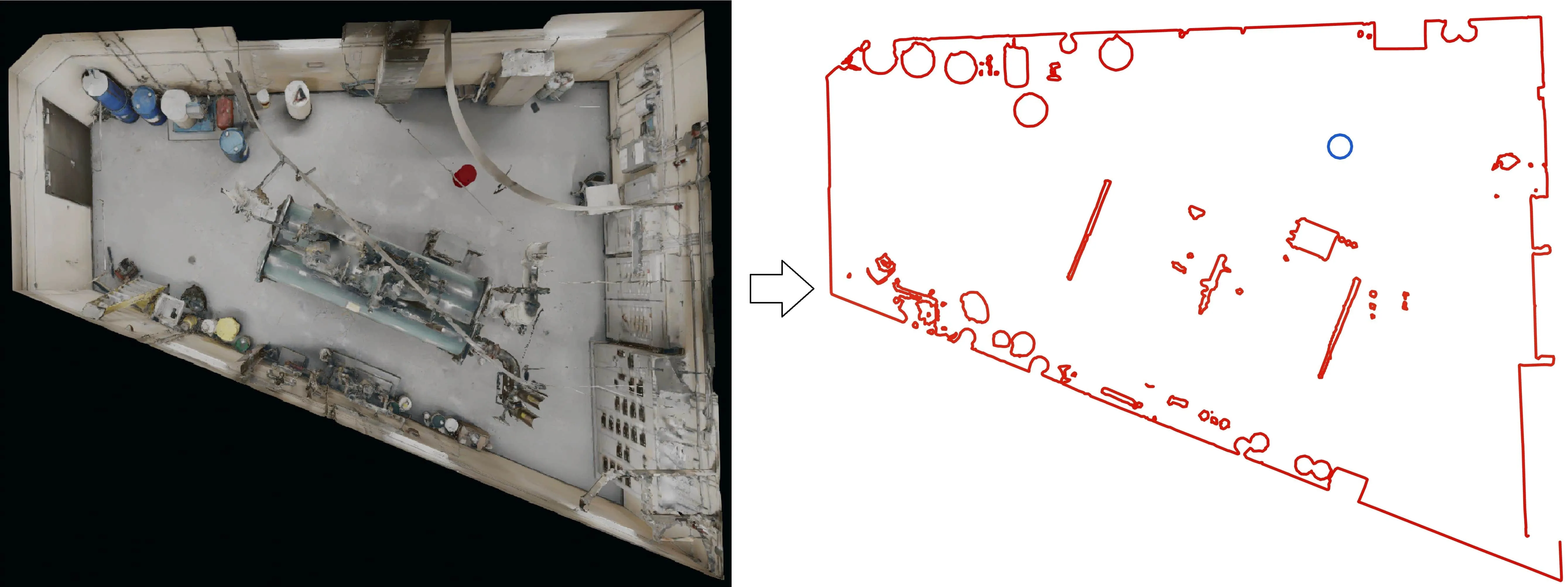
To generate a plan:
-
Select the export -> floor plan tool in the toolbar
-
Adjust the height of the slice you want to make a floor plan with
-
Choose whether you want to include the 3D models and measures in the floor plan
-
Click on Export to save the plan as an image (PNG, JPEG) or as a DXF file (AutoCAD)
Floor plan settings
Section titled “Floor plan settings”| Setting | What it does |
|---|---|
| Clipping box | Restricts the plan to one zone. Select Environment to slice the whole environment, or select a clipping box to keep only what is inside it. |
| Multiple layer plan | Slices at several heights instead of one. Each slice is kept separate in the generated plan, at its own height level, rather than being flattened into a single outline. Adds a double slider for the span and a plan density control. |
| Include shapes in plan | Adds the primitives you created (plane, cube, cylinder) to the plan — see Basic 3D Shapes. In the DXF they are drawn with blue lines, while the environment is drawn with red lines. |
| Include objects in plan | Adds 3D models — both models brought in with Import 3D and RealityAssets that were cut out of the environment and moved elsewhere. They are also drawn with blue lines. |
| Quality | Selects which level of detail is loaded from the tiling system for the environment. High picks the highest level available, for the most accurate representation of the geometry; Medium picks a level in the middle; Low picks a coarser level and is the fastest. |
| Simplify | A post-process that reduces the number of points on the exported polylines. It produces a lighter, easier-to-edit DXF, at the cost of some fidelity on curves. |
| Plan’s height | The height of the slice through the environment, shown in the viewport as a pink line. |
Generate an orthophoto (orthographic image)
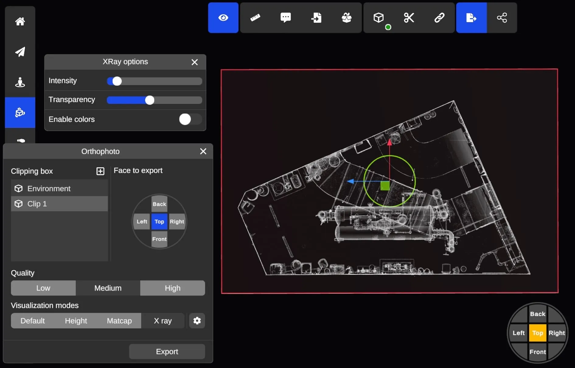
Section titled “Generate an orthophoto (orthographic image)”Using the Clipping Box tool, you can generate orthophotos using various visualization modes. Using the face selector, you can easily select the face you would like to export as an orthophoto.
The face that will be exported is always highlighted in red and you may resize the section of the face export by using the mouse to resize the clipping box.
Orthophoto settings
Section titled “Orthophoto settings”| Setting | What it does |
|---|---|
| Clipping box | Restricts the orthophoto to one zone. Select Environment to export the whole environment, or select a clipping box to keep only what is inside it. |
| Face to export | Which face of the box is rendered: Top for a plan view, or Back, Left, Right and Front for elevations. |
| Quality | Sets both the pixel density of the image and the level of detail loaded from the tiling system. See Export resolution. |
| Visualization modes | Renders the orthophoto with Default, Height, Matcap or X ray shading. X ray is often the best choice, as it brings out edges and outlines that are hard to read in the colored point cloud. Each mode has its own settings, reachable from the gear icon next to the selector. |
| Transparent background | When enabled, areas where no environment is visible are exported as transparent instead of black, so the orthophoto can be layered over a drawing or a map. |
Supported formats
Section titled “Supported formats”The following formats are supported for orthophotos export:
| Extension | Type | Comment |
|---|---|---|
| PNG | Image | A single image. Capped at 16,384 px on the longest side. |
| PGW | World file, written alongside the PNG | A small text file recording the orthophoto’s real-world position and scale, so the PNG lands at the correct place and size when loaded into GIS or CAD software instead of having to be aligned by hand. |
| DXF | DXF with XREF images | Exported as image tiles rather than one merged image, so there is no resolution cap. You may have to reload the XREF images in AutoCAD for them to appear. Opening DXF with XREF images is only supported with Autodesk viewers (AutoCAD etc.) |
Export resolution
Section titled “Export resolution”The resolution of an orthophoto is the physical size of the exported face multiplied by the pixel density of the quality setting:
| Quality | Minimum pixel density | Resulting ground sample distance (GSD) |
|---|---|---|
| Low | 50 px/m | 2 cm per pixel |
| Medium | 100 px/m | 1 cm per pixel |
| High | 200 px/m | 0.5 cm per pixel |
At Medium quality, a 40 m x 30 m face is exported at 4,000 x 3,000 px, and a 160 m x 120 m face at 16,000 x 12,000 px.
Quality also selects the level of detail loaded from the tiling system for the render, so High produces both a finer image and a more detailed representation of the environment.